Components Project
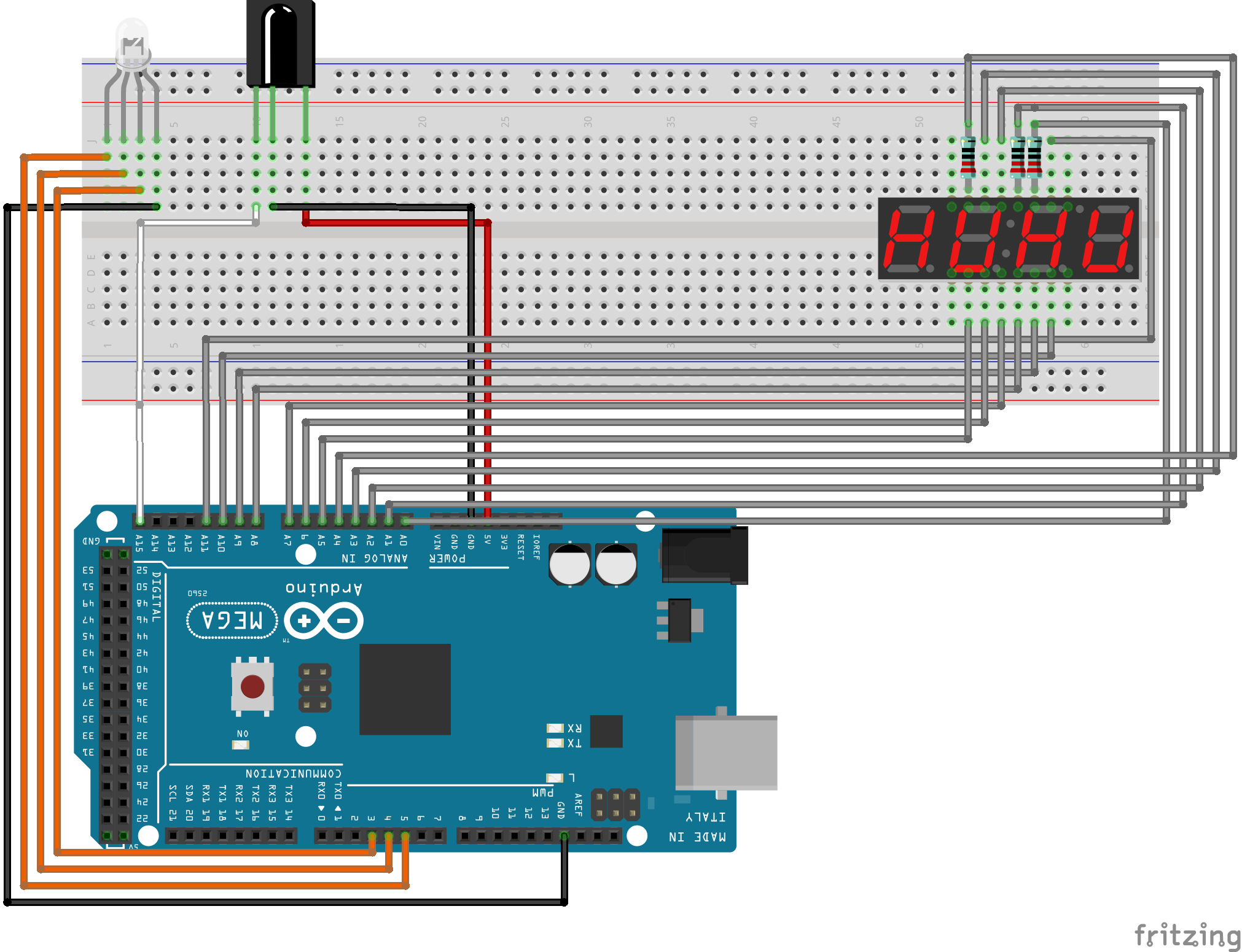
This circuit uses an infrared receiver to read the signal from a remote control and change the status of the RGB LED according to the pressed button.
Components
To set the circuit you need:
- 1 x Arduino
- 1 x Breadboard
- 1 x Infrared receiver
- 1 x Remote control
- 1 x LED RGB
- 1 x four 7 segments display
- 3 x Resistors 220Ω
- 19 x Wires
Infrared receiver
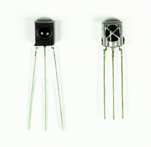 Infrared receivers often occur this way, with a round upper part
and three legs that represent anode, cathode and input pin to read the signal.
To set this item, you need to
import the library
and write the code written below:
Infrared receivers often occur this way, with a round upper part
and three legs that represent anode, cathode and input pin to read the signal.
To set this item, you need to
import the library
and write the code written below:
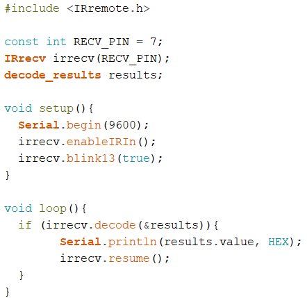 In this way we set the input pin, the variable that contains the results of
signals and the object representing the receiver. In the setup method we activate it and
we use the blink13() method to turn on a feedback light in the Arduino
when a signal has been received. The hexadecimal value of the received signal is printed each time one
is received. It is important to remember that almost every type of remote control transmits a signal
to the receiver.
In this way we set the input pin, the variable that contains the results of
signals and the object representing the receiver. In the setup method we activate it and
we use the blink13() method to turn on a feedback light in the Arduino
when a signal has been received. The hexadecimal value of the received signal is printed each time one
is received. It is important to remember that almost every type of remote control transmits a signal
to the receiver.
LED RGB
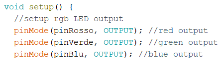
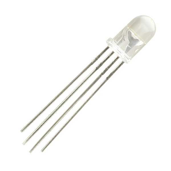 RGB LEDs consist of a pin representing the cathode and three pins for the red, green and blue colors.
They work relatively easily and similar to normal LEDs, so just plug in the pin
for each color and set it as an output pin.
RGB LEDs consist of a pin representing the cathode and three pins for the red, green and blue colors.
They work relatively easily and similar to normal LEDs, so just plug in the pin
for each color and set it as an output pin.
4 display 7 segments
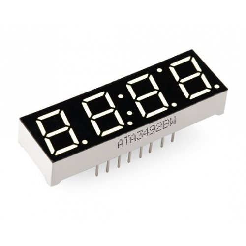
This component consists on four 7 segments displays lined up. It works in a similar way
to the single display, the difference is that you have to define which of the four to use
before turning on one of the seven LEDs (eight with the dot). It can be set via the
libraries, but it may be more intuitive to use them one at a time and set it manually.
Here there is an example of how to do this:
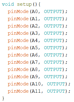
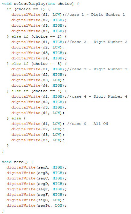
By doing this you set all the pins as output, since four of these are for define the display, and the other eight for the LEDs. The other two methods define precisely which led to use and which LEDs of the display turn on (in this case the number 0 will appear).
Download Project