Final Project
This project uses a joystick that creates a small animation on the LED matrix.
Components
To set up the project you need:
- 1 x Arduino
- 2 x Breadboard
- 1 x Joystick
- 1 x LED matrix
- 29 x Wires
Joystick
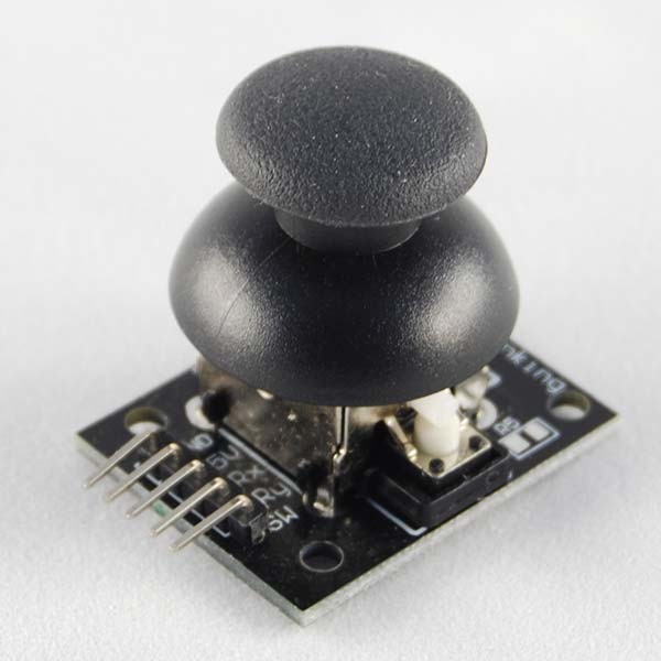 Joysticks often occur this way, with a round upper part to use it
and five legs that represent anode, cathode, input pin to read the signal and
the entries that read the horizontal and vertical coordinates. To set this up this
element libraries are not required, but the lines of code below must be written.
Joysticks often occur this way, with a round upper part to use it
and five legs that represent anode, cathode, input pin to read the signal and
the entries that read the horizontal and vertical coordinates. To set this up this
element libraries are not required, but the lines of code below must be written.
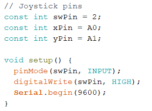 In this way we set the input pins and the coordinate pins. So in the setup method you set the input pin
as an input and activate it.
In this way we set the input pins and the coordinate pins. So in the setup method you set the input pin
as an input and activate it.
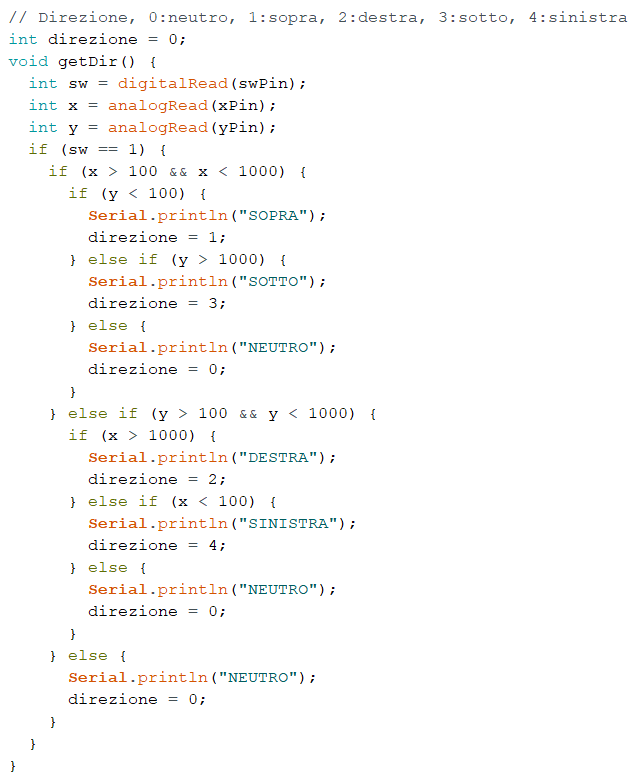 So to verify the operation you can use a method like getDir() that takes
the position of the joystick to print it at the terminal and store it into a variable.
At first ou read the entries, then find the interval for each joystick position by
reading the output of x and y, finally you can find each joystick position and
test the operation by printing the result in the terminal.
So to verify the operation you can use a method like getDir() that takes
the position of the joystick to print it at the terminal and store it into a variable.
At first ou read the entries, then find the interval for each joystick position by
reading the output of x and y, finally you can find each joystick position and
test the operation by printing the result in the terminal.
Matrice di LED
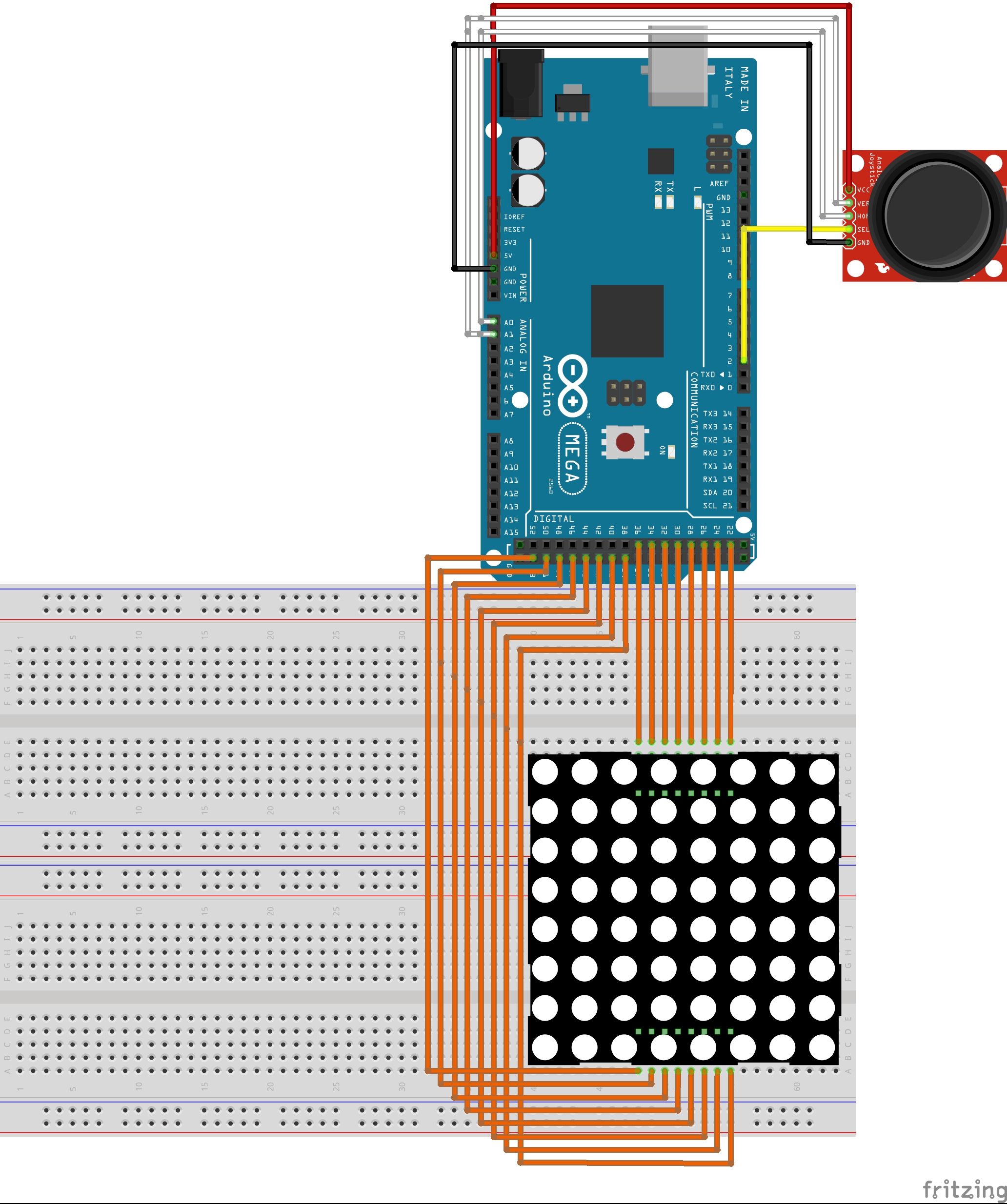
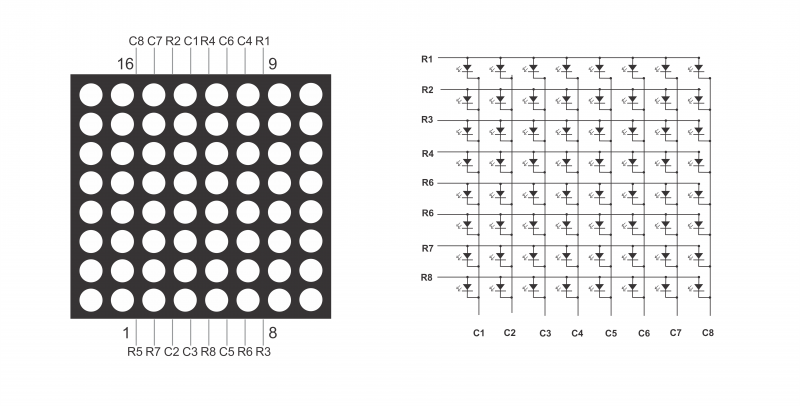 LED matrices work on the basis of rows and columns, in fact the output pins
are 16. The image explains well how the pins are attached, so the rows represent
the GND, while the columns the positive pole. To turn on the whole matrix, attack
correctly the pins and give GND to the lines and + 5V to the columns.
LED matrices work on the basis of rows and columns, in fact the output pins
are 16. The image explains well how the pins are attached, so the rows represent
the GND, while the columns the positive pole. To turn on the whole matrix, attack
correctly the pins and give GND to the lines and + 5V to the columns.
 In the code of the image the central columns light up.
Download Project